

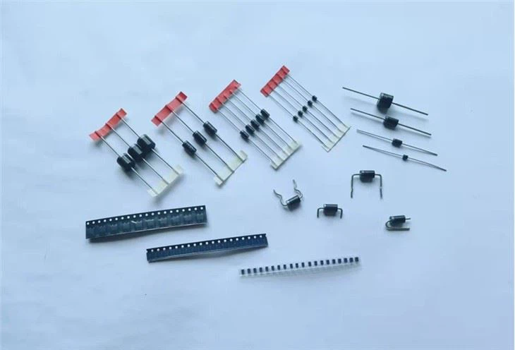
Hey there! As a supplier of 1N5819, I've had my fair share of customers asking about how to accurately measure the forward voltage of this little component. In this blog post, I'll break down the process step by step and share some tips to ensure you get the most precise readings.
First off, let's understand what the forward voltage of a diode like the 1N5819 means. The forward voltage is the voltage drop across the diode when it's conducting current in the forward direction. For the 1N5819, which is a Schottky diode, this voltage is typically lower compared to regular diodes. It's an important parameter because it affects how the diode will perform in a circuit.
Now, why is it so crucial to measure the forward voltage accurately? Well, in a lot of electronic applications, even a small variation in the forward voltage can have a big impact on the overall performance of the circuit. For example, if you're designing a power supply circuit, an inaccurate forward voltage measurement could lead to incorrect voltage regulation, which might damage other components in the circuit.

So, how do we go about measuring the forward voltage of the 1N5819? Here's a simple setup you can use:
Step 1: Gather Your Tools
You'll need a few basic tools for this measurement. First, you'll need a power supply. A variable DC power supply is ideal because it allows you to adjust the voltage easily. You'll also need a multimeter, which you'll use to measure the voltage across the diode and the current flowing through it. And of course, you'll need the 1N5819 diode itself.
Step 2: Set Up the Circuit
Connect the positive terminal of the power supply to the anode (the positive side) of the 1N5819 diode. Then, connect the cathode (the negative side) of the diode to the negative terminal of the power supply through a resistor. The resistor is used to limit the current flowing through the diode and prevent it from getting damaged. A good value for the resistor might be around 100 ohms, but this can vary depending on your specific setup.
Step 3: Measure the Current
Set your multimeter to the current measurement mode (usually denoted by an "A" for amperes). Connect the multimeter in series with the diode and the resistor. This means that the current flowing through the circuit will also flow through the multimeter. Adjust the power supply voltage until you get the desired current flowing through the diode. For the 1N5819, a common test current is around 1A, but you can refer to the datasheet for the exact specifications.
Step 4: Measure the Voltage
Once you've set the desired current, switch your multimeter to the voltage measurement mode (usually denoted by a "V" for volts). Connect the multimeter across the diode, with the positive probe on the anode and the negative probe on the cathode. The reading on the multimeter is the forward voltage of the 1N5819 at the specified current.
Tips for Accurate Measurement
- Use a Good Quality Multimeter: A cheap or inaccurate multimeter can give you false readings. Invest in a good quality multimeter that has a high level of accuracy.
- Keep the Temperature Constant: The forward voltage of a diode can vary with temperature. Try to measure the forward voltage at a constant temperature, preferably at room temperature (around 25°C).
- Check the Datasheet: The datasheet of the 1N5819 provides valuable information about the typical forward voltage at different currents. Compare your measurement with the datasheet values to make sure you're getting reasonable results.
Now, let's talk about some common mistakes to avoid when measuring the forward voltage of the 1N5819.
Common Mistakes
- Incorrect Polarity: Make sure you connect the diode in the correct direction. If you connect it backwards, you won't get a forward voltage reading, and you might even damage the diode.
- Not Limiting the Current: Without a resistor to limit the current, too much current can flow through the diode, causing it to overheat and potentially burn out.
- Ignoring the Resistance of the Wires: The resistance of the wires in your circuit can affect the measurement. Try to use short, thick wires to minimize the resistance.
In addition to the 1N5819, we also supply other Schottky diodes like the SR5100 and the SR240. These diodes have different specifications and are suitable for different applications. If you're interested in learning more about them or need help choosing the right diode for your project, feel free to reach out to us.
If you're in the market for high-quality 1N5819 diodes or any of our other products, we'd love to hear from you. Whether you're a hobbyist working on a small project or a large-scale manufacturer, we can provide you with the components you need at competitive prices. Contact us today to start the procurement process and discuss your specific requirements.
In conclusion, measuring the forward voltage of the 1N5819 accurately is essential for ensuring the proper performance of your electronic circuits. By following the steps outlined in this blog post and avoiding common mistakes, you can get reliable and precise measurements. If you have any questions or need further assistance, don't hesitate to contact us. We're here to help you make the most of our 1N5819 diodes and other products.
References
- 1N5819 Datasheet
- Electronic Circuit Design Handbook